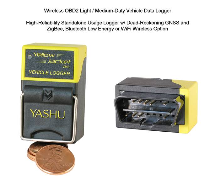
Inclinometer Pitch and Roll Tilt Sensor ISO
2631
Yashu Systems Design Services and Core Competencies
Research and Development of Hardware / Firmware / Software for
Ground Based Vehicles
• Design of Stochastic State-Space Models : Process and
Observation Definitions
• Development of Motion Control Algorithms using Closed-Loop
Sensor Feedback Topologies
• Innovation of Adaptive Stability Control Methods : Formulation,
Implementation and Analysis
• Bayesian Modeling : Conception and Experimentation as
applied within Sensory Networks
• Fusing of RTK GPS + UWB RTLS + IMU + CAN Kinematics for Out
/ Indoor Geofencing Control
• ToF IR Camera Design with application to CAN-Based
Anti-Collision Control
• Research of Autonomous Navigation using SLAM and Structure
from Motion Techniques
• Active Suspension Control Research using
Magneto-Rheological (MR) Shock Technology
Mechatronic Systems Analysis and Control Design : Custom
Hardware, Firmware and Software
• Design of CAN-Based Smart Motion Sensors with Embedded
Real-Time Kinematics Modeling
• Creation of MEMS-Based Devices and Formulae to Quantify
Suspension Motion and Ride Comfort
• Design of All Hardware Electronics, Mechanical Enclosures
and Production Test Apparatus
• Compose Software and Firmware for All Devices including
Risk Management Methodologies
• Perform Patentability Studies including Prior Art
Assessment of Infringement and Invalidity
Design of Wireless J1979 / J1939 / CANopen Telematics Data
Loggers with Aux Sensor Support
• Extended Kalman Filter Dead Reckoning Navigation Algorithms
Design (GNSS+MEMS+CAN)
• Windows Software GUI and Android / iOS BLE App Development
for Data Config / Retrieval
• Logging of Isochronous Raw Data, Processed Parameters and
Events with Cloud Upload Apps
Design of WiFi-Meshed Audio / Lighting Node for Passenger
Service in Avionics Fuselage Cabin
• Synchronized Dimmable R/G/B/W Lighting and Voice Broadcast
across all Networked Nodes
• Low-Bit-Rate Broadcast Compressed Audio using Custom
SubBand ADPCM Companding
• Adaptive Periodic Noise / Echo Cancellation of Live
Microphone Broadcasts across all Nodes
• Mobile Microphone Paging Feedback Suppression using UWB
Real-Time Location System
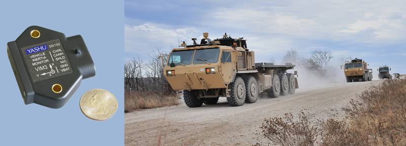
Yashu Systems : Vehicle Inertia Monitor supports Automatic
Terrain Identification
for the U.S. Army's Autonomous Convoy
Press Release : Yashu
Systems Vehicle Inertia Monitor supports Automatic Terrain Detection System
Yashu Systems : Vehicle Inertia
Monitor supports Dennis-Eagle
Prototype Hybrid EV Energy Research
Study
Press Release :
Yashu Systems Vehicle Inertia Monitor supports Dennis-Eagle Hybrid EV Research
Study

|
|
|
|
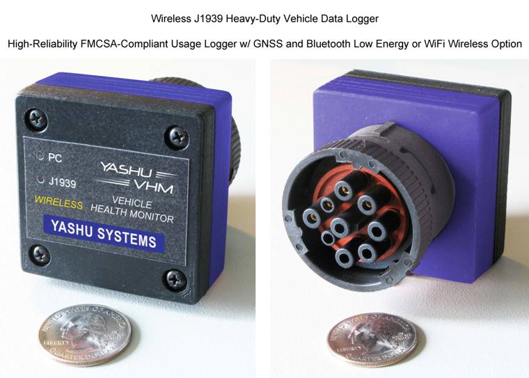
J1939
Wireless Vehicle Health Monitor Specifications |
|
|
YellowJacket
Vehicle Management System Specifications |
|
|
|
|
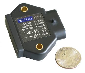
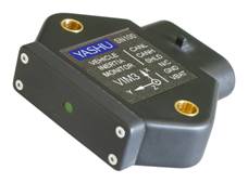
J1939 Vehicle Inertia
Monitor VIM
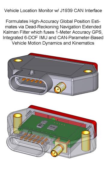
Formulates Moving Vehicle
Pitch and Roll Tilt Estimates using Multiple Sensor Fusion
J1939 Vehicle Inertial
Measurement and Vibration Monitoring Device
|
|
|
|
|
|
|
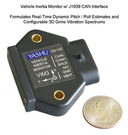
The Vehicle Inertia Monitor is not a typical
digital inclinometer that is commonplace in the J1939 market. These commodity
inclinometers are intended for static environments where the vehicle is not
moving and therefore generate significant pitch / roll errors when the
vehicle accelerates, decelerates or turns. The VIM incorporates advanced signal processing
techniques using dynamic modeling and detected vehicle motion from the J1939
communication link. This results in extremely accurate pitch / roll estimates
when the vehicle is in motion. Additionally the VIM filters noise from these
attitude estimates via sensor data fusion within an Extended Kalman Filter to
provide fast, smooth data results in real-time. |
|
New Standard Features: • High Accuracy Grms Vibration
Capability with 200 microGrms Resolution • Improved Vibration Frequency
Spectrum J1939 MultiPacket Transmission • Vehicle 3D Instantaneous
Displacement Estimates via Extended Kalman Filter ♦ Proprietary
Stochastic State-Space Prediction + Observation Processes |
|
** Now
Available ** • ISO 2631
Human Vibration Dosage Levels Monitoring Mode ♦
ISO 8041 Compliant : Frequency Weightings for Wb-c-d-e-f-j-k ♦
Real-Time Updates for Aw, RunningRMS Aw, MTVV, MSDV + VDV ♦
Double Precision Cascaded Bi-Quad IIR Filters Implementation |
|
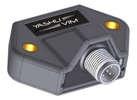
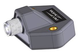
VIM with 5-Pin M12
Connector and NEMA2000 Standard Pinout |
||||
|
|
|
|
||
|
Coming Soon : Pre-Production CAD Render Shown
Above |
||||
|
|
||||
|
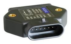
Accident Detection Sensor
(ADS) |
||||
|
ADS with 8-Pin M12
Connector (J1939 + Discrete I/O) and USB Maintenance Port |
||||
|
|
|
|
||
|
Coming Soon : Pre-Production CAD Render
Shown Above |
||||
Basic Features:
DSP Microcontroller
Hosts Advanced Data Processing Algorithms and Applications
J1939 CAN
Bus Interface to Acquire and Transmit Vehicle Data used in Parameter
Calculations
Single Low
Cost Automotive Grade 6-Contact Connector for Power and CAN Bus : TriColor Status
LED
Thick
Walled ABS Plastic Enclosure with Brass Press Inserts : 1.9” L x 2.3”
W x
0.56” H
-40C to
+85C
Core Capabilities:
Integrated
MEMS Accelerometer and Gyroscope support Moving Vehicle Pitch and Roll
Estimates
3-Axis
Vibration Monitoring of SubBand Frequency Grms-Force Levels with Optional Order
Tracking
Vehicle Attitude Monitoring Features:
Incorporates
Vehicle Kinematic Model and Kalman Filtering for Real-Time Attitude Estimates
• Uses CAN Parametrics, MEMS Sensor Data and
Vehicle Frame Dimensioning
• Gyroscope + Accelerometer Data Fusion via
Advanced Kalman Filtering
• Performs Compensation for Vehicle Frame
Longitudinal and Lateral Accelerations
• Unique Gyroscope Precession Compensation
supports Vehicle Maneuvers on Inclined Surfaces
Supports
Arbitrary VIM Mounting Location and Rotation when affixed to Vehicle Frame
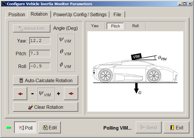
• Integrated User-Interactive Calibration
Functions simplify formulations of:
♦ VIM
Mounting Rotation Matrix using Yaw, Pitch and Roll
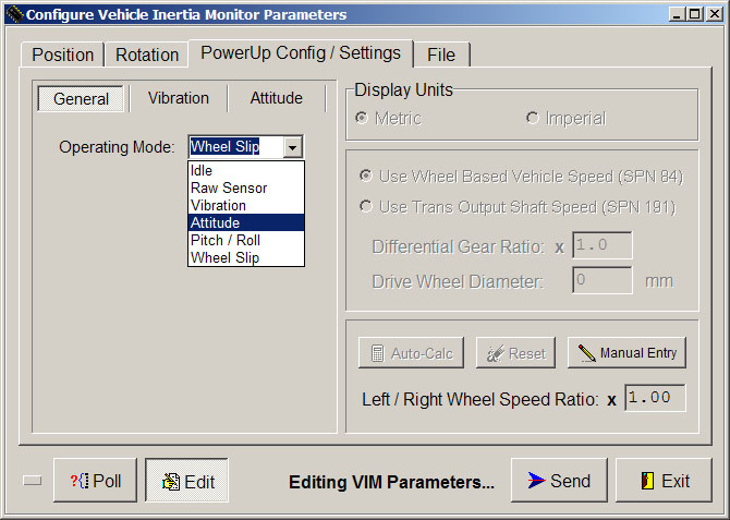
♦
Vehicle Drive Wheel Speeds Difference Correction Factor
Vibration and Health Monitoring Features:
3-Axis
Selectable Sensitivity / Bandwidth Vibration Monitoring Device with J1939
Interface
• Selectable AC / DC Coupling with Full Scale
Vibration Ranges of:
♦ ± 2G
max or
± 6G max @ 200uGrms SubBand Grms Value Quantization
♦ < 4mGrms
typ noise level @ 2Khz BW (Post FFT-Based Parseval’s Theorem Processing)
♦ <
1mGrms typ noise level @ < 300Hz BW (Post FFT-Based Parseval’s Theorem
Processing)
• 45dB Typ Instantaneous Dynamic Range with
Configurable Bandwidth / Resolution of:
|
BW (Hz) |
Res (Hz) |
BW (Hz) |
Res (Hz) |
|
60 |
0.156 |
600 |
1.25 |
|
140 |
0.313 |
1200 |
2.5 |
|
300 |
0.625 |
2000 |
5 |
Real-Time
Grms Level Monitoring within Configurable Frequency SubBands
• SubBand Frequency Order Tracking to a Configurable
J1939 Sync Parameter
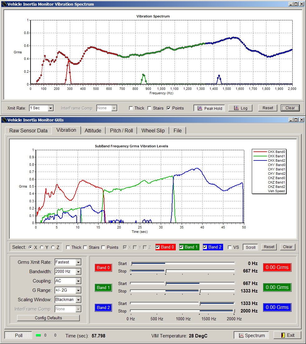
Real-Time
Spectrum Display w/ Peak Hold and Logarithmic Display Options
• Fast Update Rate across J1939 using P2P
MultiPacket Messaging
• FFT Spectral Overlapping at 25ms Frame Rate
results in No Missed Data
Advanced
Spectral or Cepstral Domain Based Gearbox Analyses and Profiling (Future)
• Multipacket P2P or BAM Transmission of Matrix
Data at Configurable J1939 Rate
• Spectrum / Cepstrum Order Tracking Support to
a Configurable J1939 Sync Parameter
• Optional Bispectrum Based Analysis Mode
combats High Noise Environments
♦
Supports transmission of Full 3D Bispectrum or Diagonal Slice Vector
♦
Selectable FFT Size, Window Type, Max Lag Vector and Biased / Unbiased
Estimate
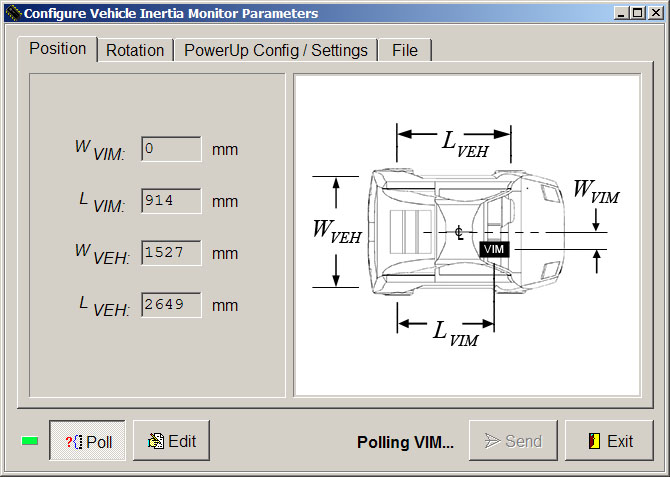
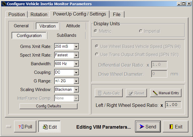
Configuration, Monitoring and Maintenance Device Utility Software:
User
Friendly Utility Software to Configure and Monitor VIM while Installed to
Target Vehicle
• Monitor Vehicle Attitude and Vibration Levels
: Real-Time Spectrum Analyzer Window Display
• Perform VIM Non-Volatile Configurations for
Operating Mode with Associated Parameters
|
VIM
Arbitrary Mounting Position
|
VIM
Arbitrary Mounting Rotation w/ AutoCal
|
|
VIM
Operating Mode and Settings Vehicle
Wheel Speeds L/R Ratio w/ AutoCal
|
VIM Vibration
Mode Parameters
|
|
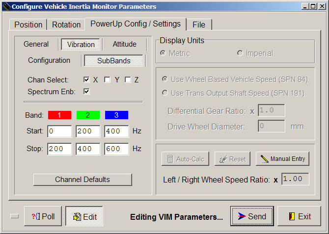
VIM
Vibration Mode SubBand Configuration
|
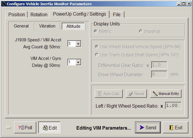
VIM Attitude
Mode Parameters
|
VIM
Specifications Sheet: VIM
Specifications Sheet (.pdf)
VIM
Stability Control App Video: VIM SCS
Application Example (YouTube)
|
The
Following Video Shows Real-Time VIM
Pitch / Roll Estimates during Vehicle Maneuvers |
VIM Vehicle Pitch /
Roll Video: VIM
Attitude Estimates Example (.wmv)
• Real-Time Attitude Estimates of Vehicle doing
Qty-2 Figure-8 Patterns on Smooth 6-Degree Ramp
• Thin Dashed Trace shows Noisy Accelerometer-Based-Only
Estimates
♦
Vehicle Frame Acceleration Compensation is Included within Accel-Only
Estimates
• Thick Solid Trace Fuses
Precession-Compensated Gyroscope Data to the Accel-Only Estimates
|
The
Following Videos Show the Weaknesses and Inaccuracies of Competing J1939
Inclinometers |
Vehicle
Pitch / Roll Video without Vehicle Frame Acceleration Compensation:
Typical
Digital Inclinometer Attitude Estimates Example (.wmv)
• Video Shows Erroneous Results from a Typical
Competing J1939 Digital Inclinometer
♦ Roll
Estimates are Permuted due to Lateral Acceleration during Turns at Top / Bottom
of Ramp
Ø VIM Solves this issue using Dynamic Kinematic
Modeling and Detected Motion of the Vehicle
VIM Vehicle Pitch /
Roll Video without Gyro Precession Compensation:
VIM
Attitude Estimates without Gyro Precession Comp Example (.wmv)
• Video Shows Kalman Estimate Overshoot
resulting from Gyro Bleed between Pitch and Roll Axes
♦
Prominent Overshoot Occurs in Pitch Estimate during Right Turn-Around at
Top of Ramp
Ø VIM Solves this issue using a 2D Plane Based
Reference to Minimize Precession Bleed
VIM
Vibration GUI Screen Shot: Swept Sine Wave on Small Speaker Diaphragm
VIM Evaluation Software : Real-Time Spectrum and Vibration GUI
|
|
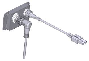
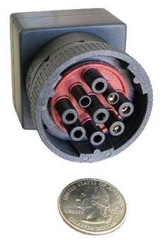
J1939 USB CAN Interface
UCI1
|
|
|
|
|
|
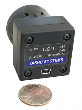
Features:
Establishes
In-Vehicle Link between Device Utility Software and Vehicle-Installed VIM
Unit(s)
Used to
Perform In-Vehicle VIM Configuration, Real-Time Data Inspection and Firmware
Upgrades
Standard
9-Pin J1939 Deutsch Locking Connector : PC Host and J1939 Bus TriColor Status
LEDs
Galvanically
Isolated USB 2.0 Interface with Standard Mini-B Connector
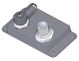
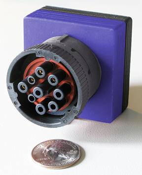
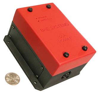
J1939 Miniature Data
Logger MDL1
|
|
|
|
|
|
|
Pre-Production Prototype Shown Above |
||||
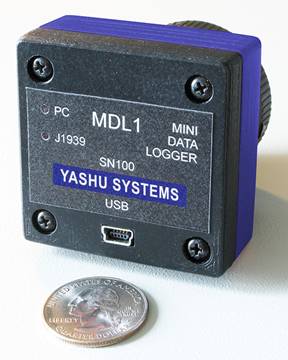
Features:
Conforms to
SAE J1939 Protocol and Mates to Vehicle’s OnBoard Diagnostic Data Connector
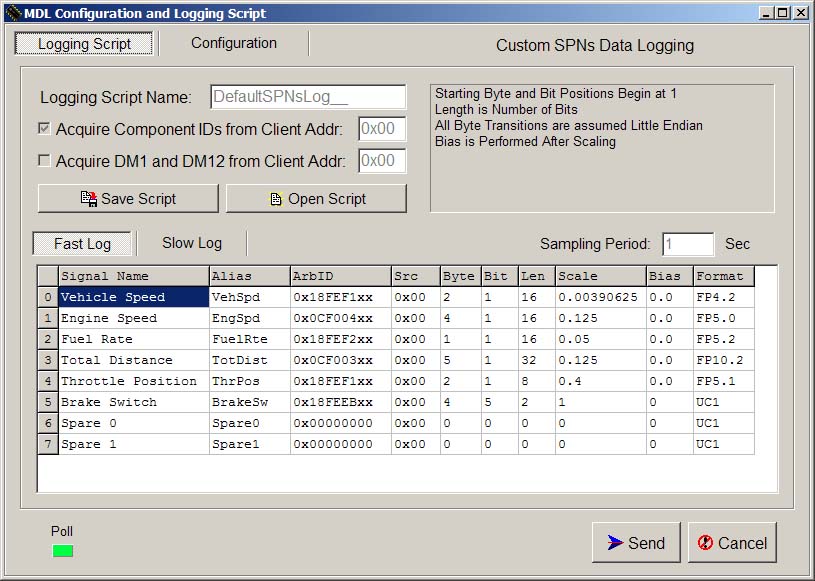
Supports
Configurable Custom SPNs Logging Scripts including DTCs and Component IDs
• Provides Capability for Multiple Simultaneous
Logging Profiles and Sampling Rates
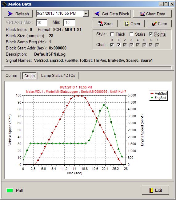
Intuitive
Data Extraction Software supports Uploading, Previewing and Saving of Logged
Information
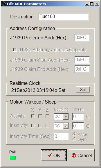
Realtime
Clock with Rechargeable Battery Backup maintains Accurate Time when removed
from Vehicle
Low Power
Sleep Mode allows Permanent Installation to Vehicle with WakeUp on Specific CAN
Activity
• Integrated MEMS Accelerometer and Gyroscope
also allows WakeUp on Motion Detect
Computes
and Logs Moving Vehicle Pitch / Roll Estimates with Compensation for Frame
Accelerations
• Incorporates Advanced Vehicle Kinematic Model
allowing for Arbitrary Mounting Location of MDL
Integrated
Backup Power Supply provides Immunity to Surprise Loss of Vehicle Power and
Brownouts
USB 2.0
Interface using Standard Mini-B Connector : Small Rugged Enclosure with Gold
Plated Contacts
Standard
9-Pin J1939 Deutsch Locking Connector : PC Host and J1939 Bus TriColor Status
LEDs
J1939 Miniature Data Logger Software : Custom SPNs Data Logging GUI
|
|
J1939 Miniature Data Logger Software : Data Retrieve and Settings GUIs
|
|
|
|
|
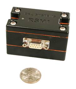
ZigBee DSP Inertia Monitor
DIM1 + Remote Sensor Monitor RSM1
- Developed by Yashu Systems for Boeing Aircraft -
- Advanced Rotorcraft Technology -
Boeing Adaptive
Vehicle Management System - Streaming Video (YouTube)
|
|
DIM1 DSP Inertia Monitor v1 |
|
RSM1 Remote Sensor Monitor v1 |
|
DIM1 Features:
Supports TC
/ RTD, Pressure, Flow, Strain, Proximity, 4-20mA, Analog and ICP Accelerometer
Sensors
Integrated
6-DOF Inertial Measurement Unit : Extended Kalman Filter provides Pitch / Roll
Estimates
2
Configurable Input Channels based on Wheatstone Bridge : 2 ICP Accelerometer
Channels
Universal
Sensor Input Channel Design supports Almost Any Sensor Type
Robust
Bridge Interface Allows for Quarter, Half or
Isolated
Programmable Constant Current Source Excitation for Each Sensor Channel
Deep Sleep
Capability with Motion Sensing Wakeup : Qty 4 AA NiMH Batteries Drawer
RSM1 Features:
Provides
Wireless Interfacing from DIM1 to a Remote Sensor : Support for Various Sensor
Types
Programmable
Gain Inst Amplifier : Floating Differential Inputs : High Capacity 2/3A Lithium
Battery
Integrated
3-Axis MEMS Accelerometer : Deep Sleep Capability with Motion Sensing Wakeup
Provides
Programmable Constant Current Sensor Excitation for Immunity to Sensor Cable IR
Losses
High Grade
Aluminum Enclosure : Waterproof / Shockproof : -40C to +85C Temperature Range
Operates
in Extreme Environments : Up to +/- 50G Continuous Acceleration Force along any
Axis